After building your sensor station its time for some testing. When all works you can roll your own firmware
Make sure the A9, the spectra 2.4 module (TX module on back of A9) and Optima 7/9 are updated with the latest firmware. Old firmware don't support telemetry!!. You can update firmware by using the HPP-22
First of all
Solderjumper Setting
To have maximum freedom in connecting sensors the Analog-To-Digital (ADC) convertor can operate with different references. The more stable this
reference the more accurate all measurements. On the back of the board (solderside) the ADC reference can be choosen using a solder jumper. See images below.
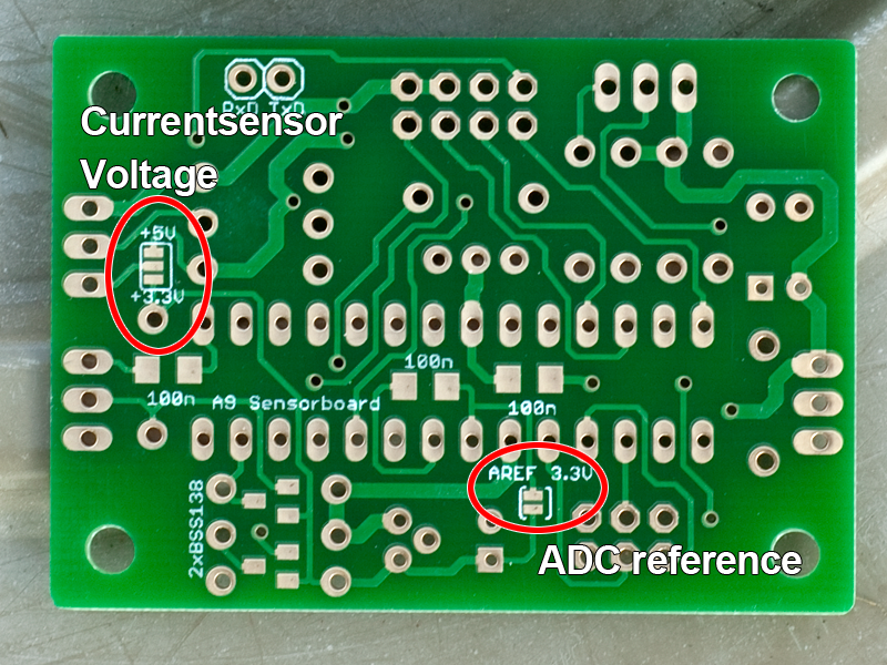
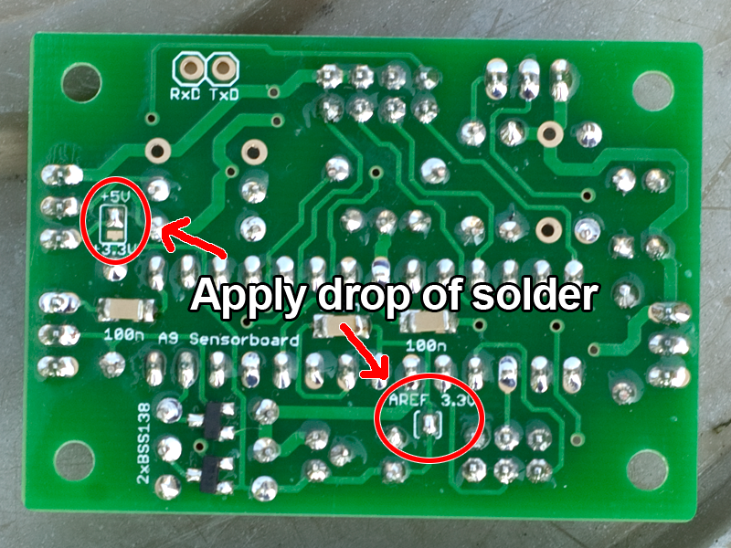
The other solderjumper determine the voltage applied to the currentsensor header. Depending on your sensor 3.3V or 5V can be selected. The currentsensor based on the ACS756 chip can work with both but 5V is preferred. See image above.
Step 1: basic
Power-up Behaviour
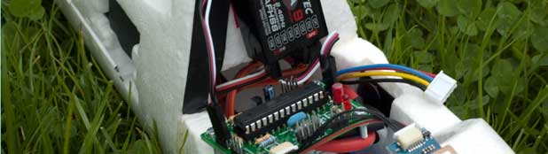
Power your sensor board using the PWR connector. The sensor board can be powered directly
from Optima 7/9 receivers, an ESC or receiver accu. Make sure the input voltage does not exceed 5.5 Volt.
Immediately after powerup the red LED should flash a few times. After that the LED flashed approx. every
2 seconds.
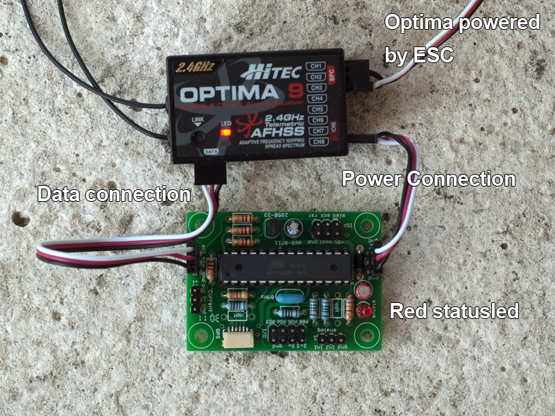
Step 2: data link
Communication
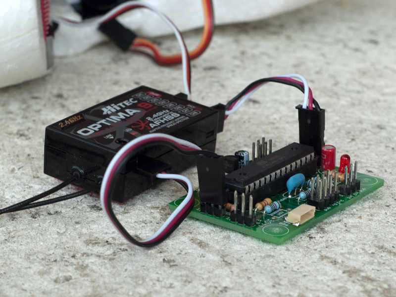
Connect the sensor station data port to the Optima 7/9 data port. Make sure the receiver is paired with
the transmitter. Switch-on the Aurora transmitter and power the Optima Receiver and the sensorboard. The A9
will beep that it has found the receiver.
Now tap the 'battery' on the A9 screen or go to 'sensors'
in the A9 menu, you will see all telemetery options available!
Step 3: connecting
Sensors
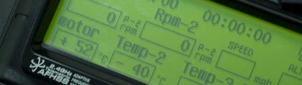
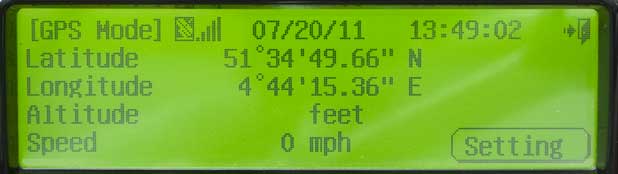
If available, plug-in the GPS and wait til the blue GPS led turns solid. Check the A9 screen and it will
show time/date, coordinates, altitude and speed information. You can check these in Google Earth. When flying,
it's actually fun to find the model's altitude and speed.
The displayed time is UTC. Tap the 'settings' button to adjust to local time.
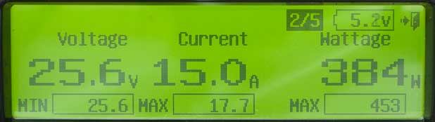
You can directly connect system voltage to the board. See 'application ideas' for more info. Remember you can set an alarm to protect your system battery. When connected the system voltage can be monitored on the A9 display.
Roll your own
Firmware
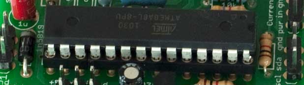
You need a ISP (In Circuit Programmer) for firmware updates. The sensor board contains a header that directly connects to the ISP. You can buy cheap In Circuit Programmers at ebay.com or build one yourself. google search or see ponyprog or here for simple parallel port based programmers.
Almost all programmers work with avrdude as programming utility. You have to tell avrdude which programmer to use. Please modify the project Makefile to make it works with your programmer (I'm using the crisp programmer, -c stk500v2 to avrdude).
Make sure you have installed the freeware avr-gcc compiler, grab and unzip the source code, open a terminal and go ahead.
To build an image from source just invoke make or make clean && make. This results in hs.hex that can be downloaded to the board.
To update the firmware, connect the programmer to your sensor station and invoke make install. This will download the newest firmware whereafter it will reset the sensor station.
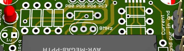
When you build the board yourself make sure the AVR runs at 8MHz, you have to set the correct configuration fuses, use fuse config: 0xDE:0xD9 when using the external 8MHz resonator. With avrdude:
avrdude -c stk500v2 -P /dev/tty.usbserial-A7005tiJ -p m8 -v -U lfuse:w:0xde:m -U hfuse:w:0xd9:m