Use a solder iron with a small tip (approx. 1 mm), use small diameter solder (approx. 1 mm) especially for the SMD components. Make sure the iron tip is always clean and shiny.
Soldering is all about heat transfer. To cold and solder joints will become bad, to long and to much heat overheats components, solderflux and PCB. Good solder joints do have a smooth, shiny surface without burned flux that shows up as ‘brown spots’. There are some good tutorials here, here and here
Click thumbnails for higher resolution.
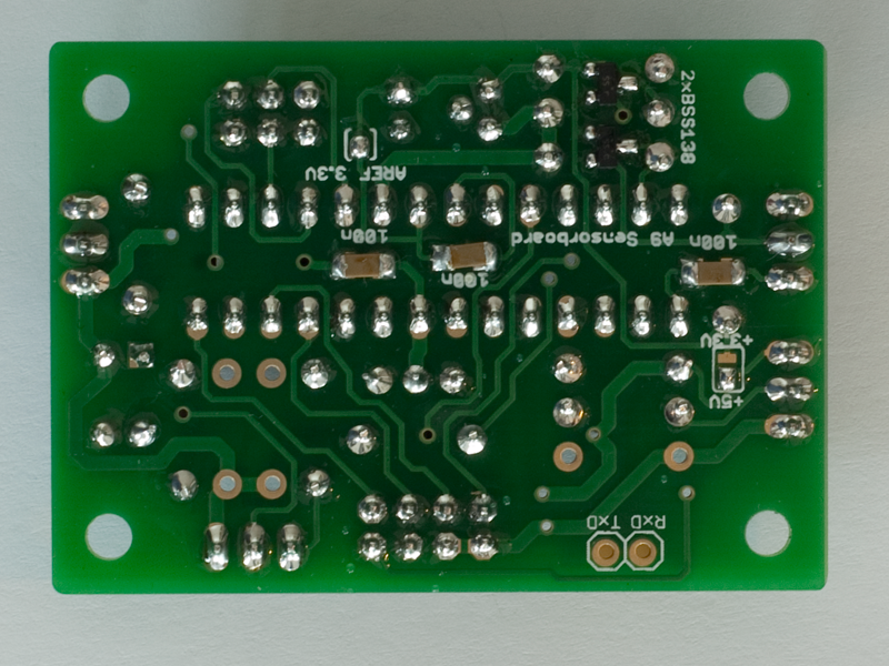
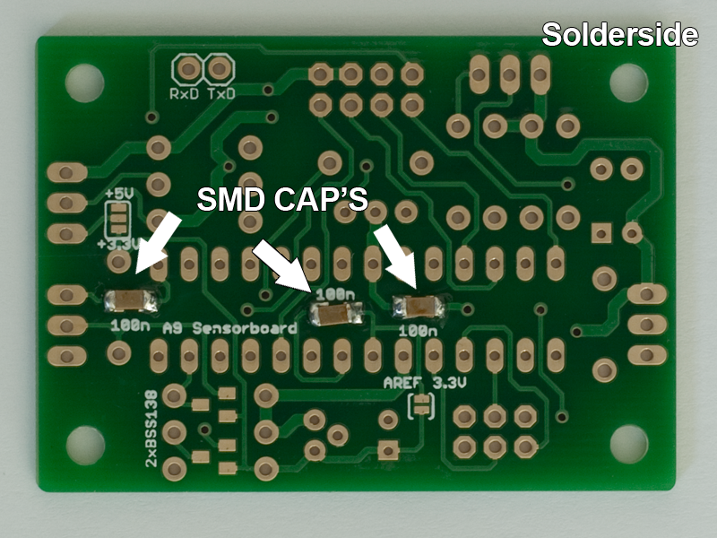
Step 1: smd capacitors
C1, C2 and C3 (100nF)
On the solder side of the PCB solder capacitors C1, C2 and C3. Polarity is not important.
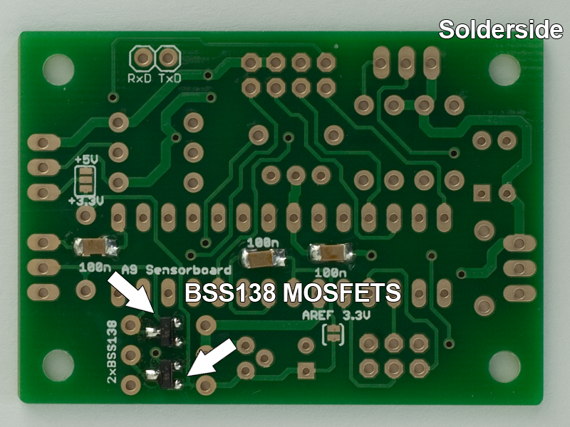
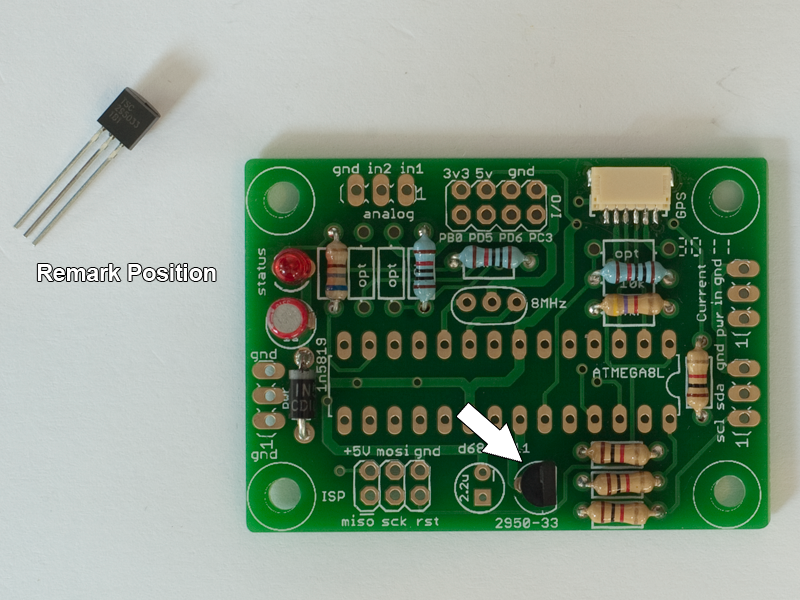
Step 2: smd MOSFETS
Q1 and Q2 (BSS138)
On the solder side of the PCB solder mosfet Q1 and Q2. Remark their position.
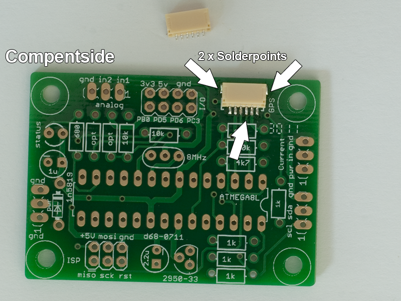
Step 3: smd connector
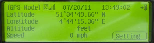
GPS connector
On the component side of the PCB solder the GPS connector. If you dont want to use the Mediatek GPS from DIY droens do not solder this connector but use the GPS breakout connector JP1 and JP2. See more in the Application Idea section.
Make sure you secure the connector to the PCB by soldering the 2 'side pads'
Step 4: normal resistor
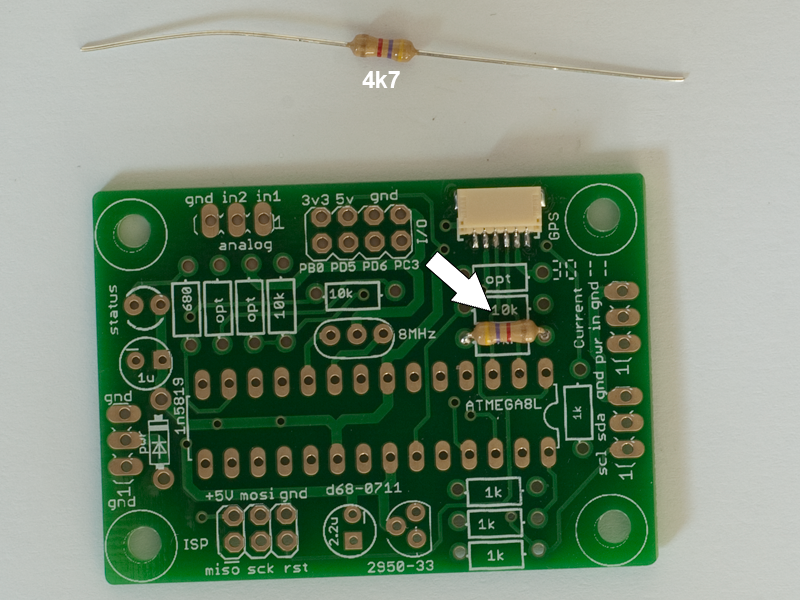
R1 (4k7)
Solder resistor R1 (mount on component side, solder on solder side). This resistor is part of the reset circuitry
Step 5: normal resistor
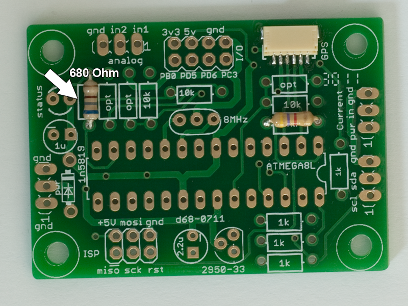
R2 (680)
Solder resistor R2. This resistor is part of the LED circuitry.
Step 6: normal resistors
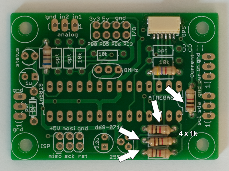
R3, R4, R5 and R6 (1k)
Solder resistors R3-R6. These resistors are part of the telemetry interface to the Optima 7/9 receivers.
Step 7: precision resistors
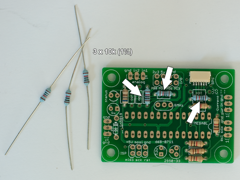
R7, R9 and R10 (10k, 1%)
Before mounting make sure you have read the Application Ideas section. These precision resistors are part of the analog input circuitry.
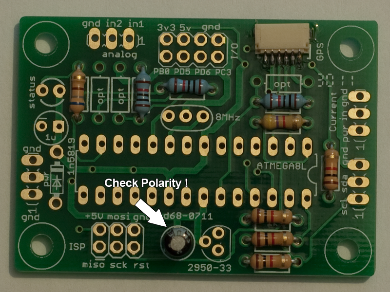
Step 8: normal capacitor
C4 (2.2uF)
This capacitor helps to stabilize the 3.3V that is used to power the interface to the Optima recievers. The 3.3V is also used as reference in the ADC (Analog to Digital Convertor). Remark orientation!
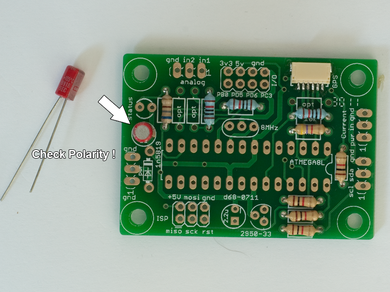
Step 9: normal capacitor
C5 (1uF)
This capacitor eleminates low frequency interference. Remark orientation!
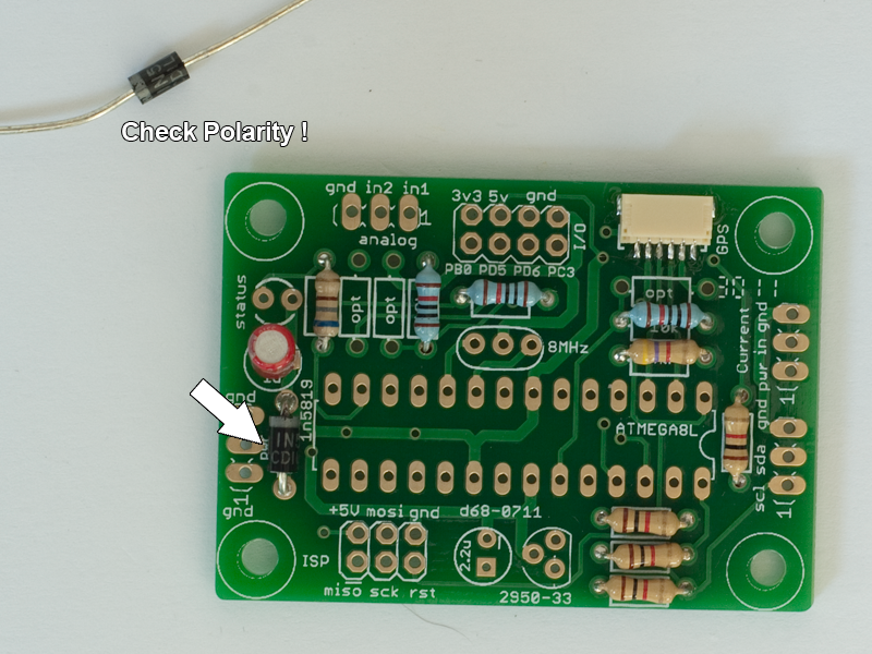
Step 10: normal schottky diode
D1 (1N5819)
Protects sensor station agains reverse polarity.Remark orientation!
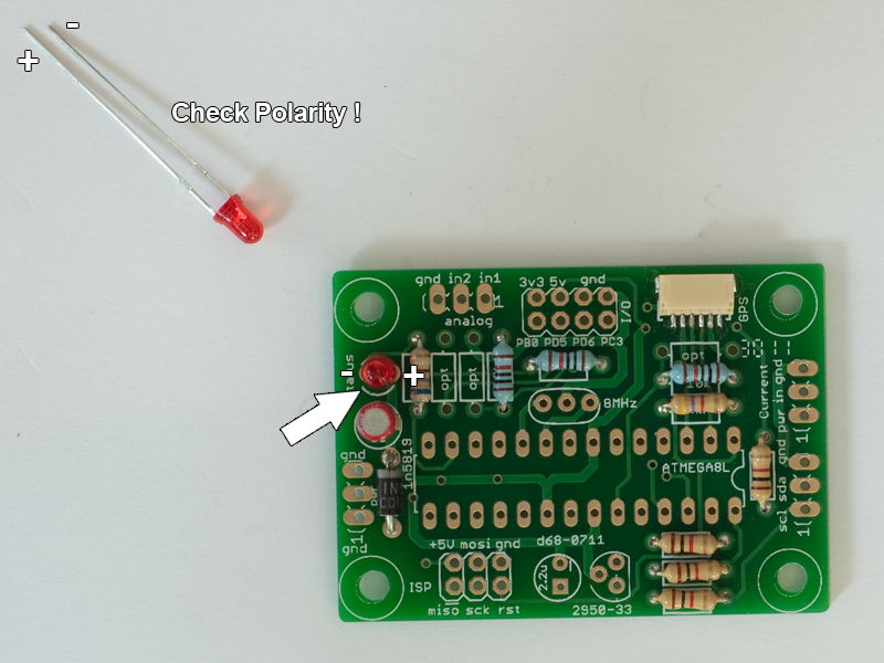
Step 11: normal LED
LED1 (3mm, red)
This is the status led. Flashes at power up, blinks when measurements are in progress. Remark orientation!
Step 12: normal Voltage regulator
IC2 (LP2950Z-33)
Converts 5V to 3.3V Remark orientation!
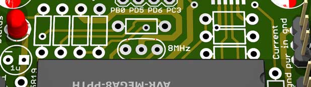
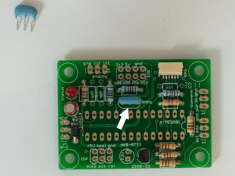
Step 13: normal Resonator
Y1 (8MHz)
Provides a accurate clock to the ATMega. Although the ATMega can generate its own, for some GPS's it is not accurate enough.
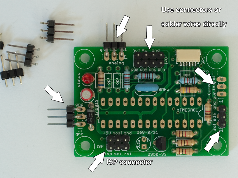
Step 14: normal connectors
ISP, PWR, I/O, ...
Connect through wires solder directly to the board or by connectors. Connectors are less reliable but more flexible. The ISP connector is mandatory if you ever want to update the firmware.
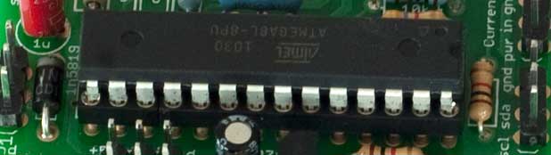
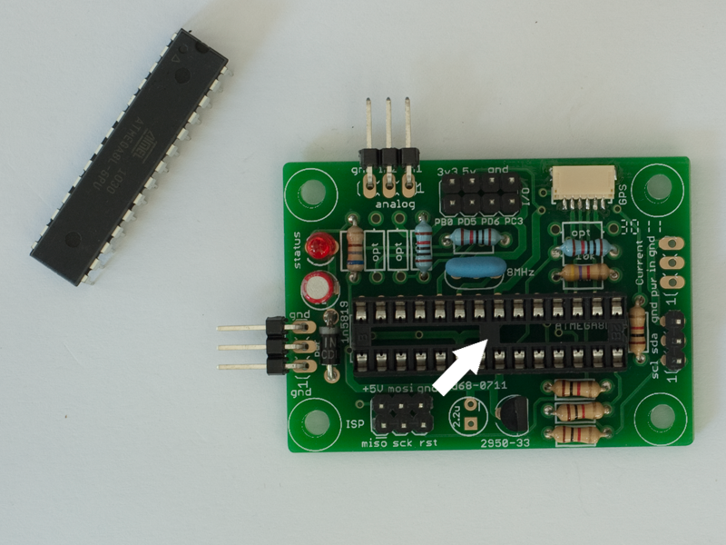
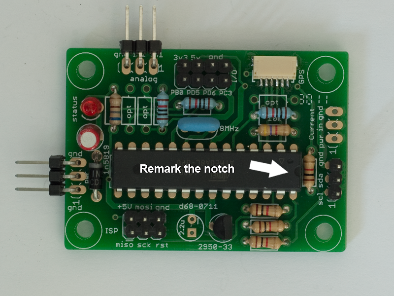
Step 15: normal microcontroller
ATMega8L
You can solder the microcontroller directly to the board or use the provided socket. Direct soldering is much more reliable than using a socket (RC vehicles crash and bumps!). But if you plan to use bigger ATMega's socketing is a better choice. Whatever you choose, firmware updating is always possible.
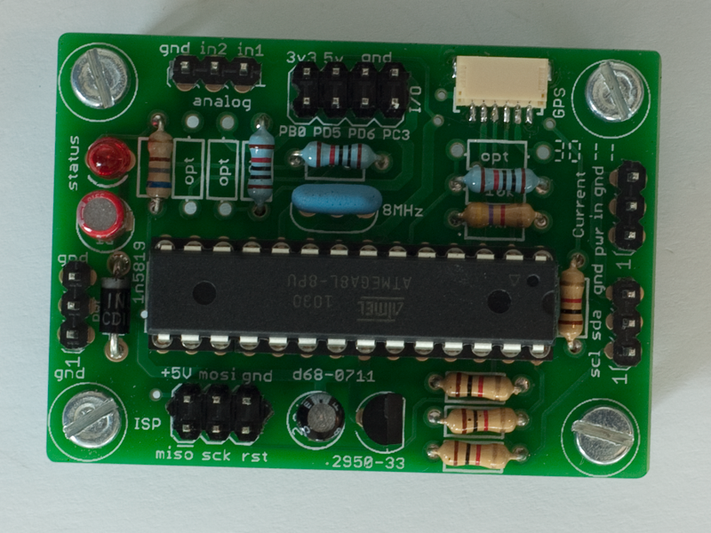
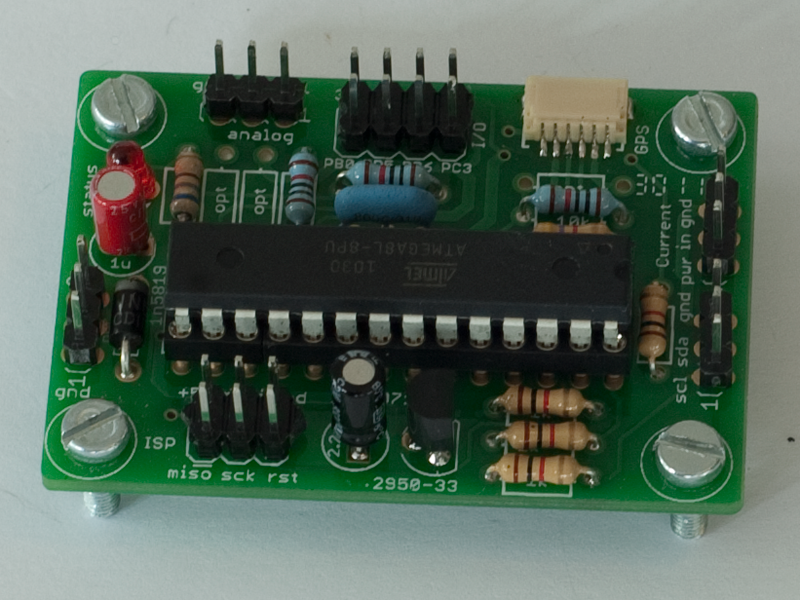
Finished
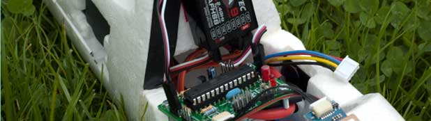
Sensor Station
You can solder the microcontroller directly to the board or use the provided socket. Direct soldering is much more reliable than using a socket (RC vehicles crash and bumps!). But if you plan to use bigger ATMega's socketing is a better choice. Whatever you choose, firmware updating is always possible.